We remain fully operational. Our teams are working around the clock to ensure your deliveries continue safely.

下载应用程序


⏱️ Upgrade your ride’s timing game—because precision waits for no one!
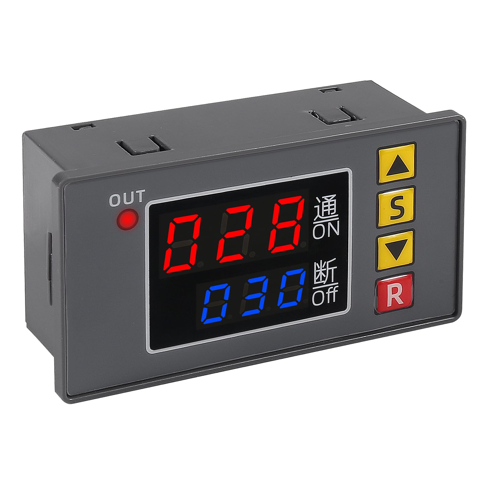
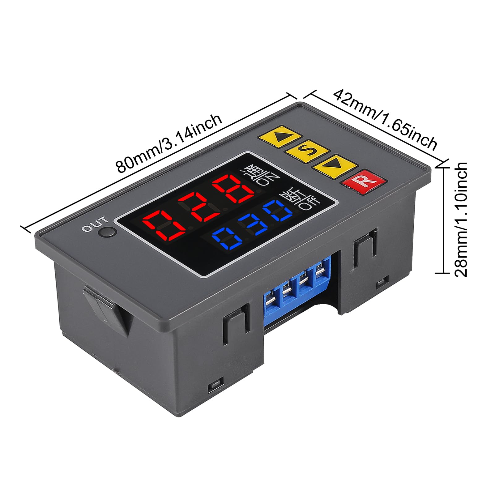
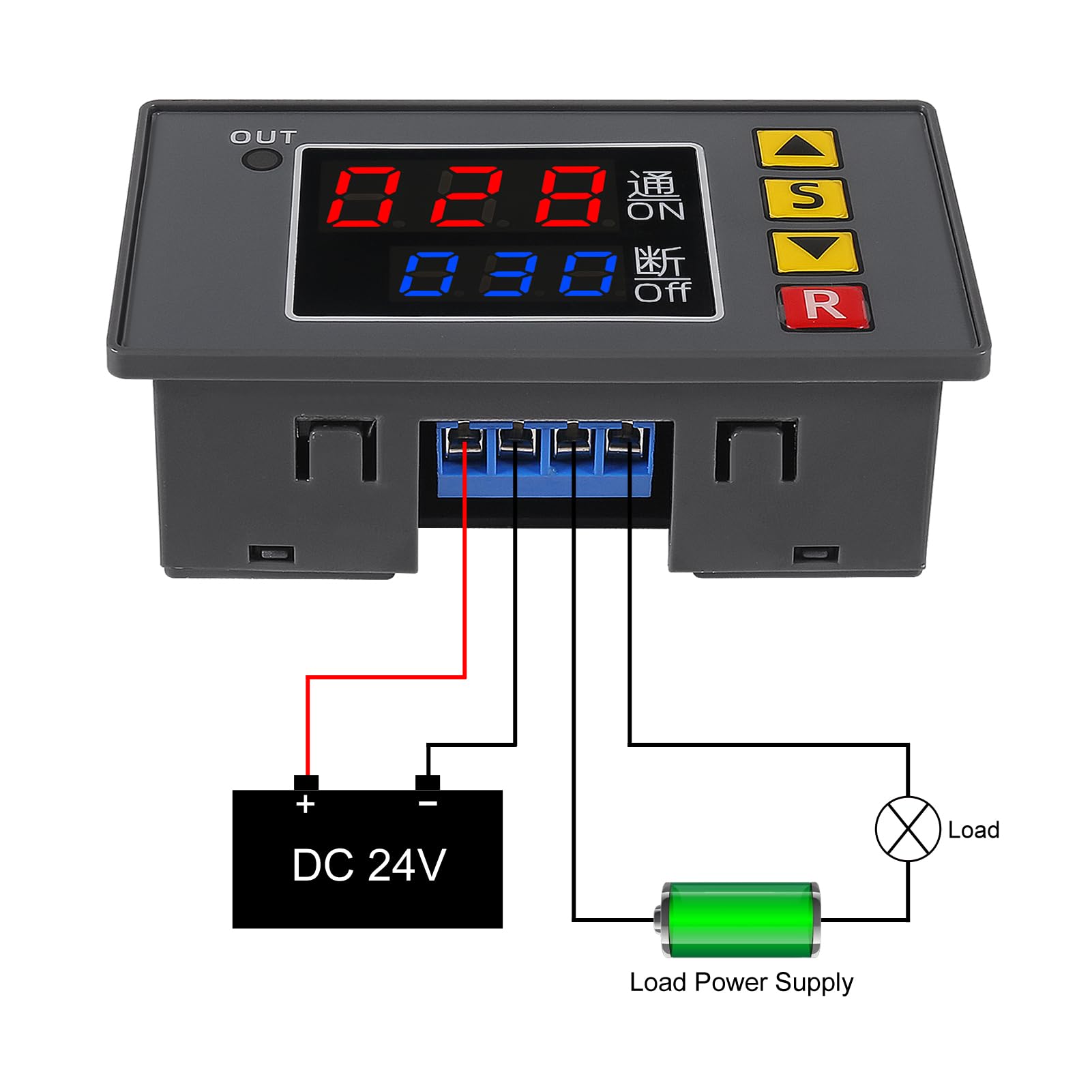
The UMLIFE Automotive Digital Timer Relay Board is a robust DC 12V module designed for precise timing control in automotive and DIY applications. Featuring a wide timing range from 1 second to 999 hours, dual LED displays for real-time and set values, and a powerful 20A/1500W relay, it supports multiple timing modes with easy button setup and non-volatile memory. Ideal for vehicle systems like hot water recirculation, cycle timing, and delay controls, this compact panel-mount module delivers reliable, customizable automation for the modern driver.
| ASIN | B081TQBNSH |
| Best Sellers Rank | #222,397 in Automotive ( See Top 100 in Automotive ) #6 in Automotive Replacement Time Delay Relays |
| Brand Name | UMLIFE |
| Coil Voltage | 12 Volts |
| Connector Type | Through Hole |
| Contact Current Rating | 20 Amps |
| Contact Material | Copper Alloy Or Silver Alloy |
| Contact Type | Normally Open |
| Current Rating | 20 Amps |
| Customer Reviews | 4.0 4.0 out of 5 stars (148) |
| Manufacturer | UMLIFE |
| Maximum Switching Current | 20 Amps |
| Minimum Switching Voltage | 12 Volts (DC) |
| Mounting Type | Panel Mount |
| Operating Time | 999 Hours |
| Operation Mode | Automatic |
| Part Number | 1 |
| UPC | 701715431430 |
| Wattage | 1500 watts |
C**S
Great timer for RV hot water recirculation plumbing
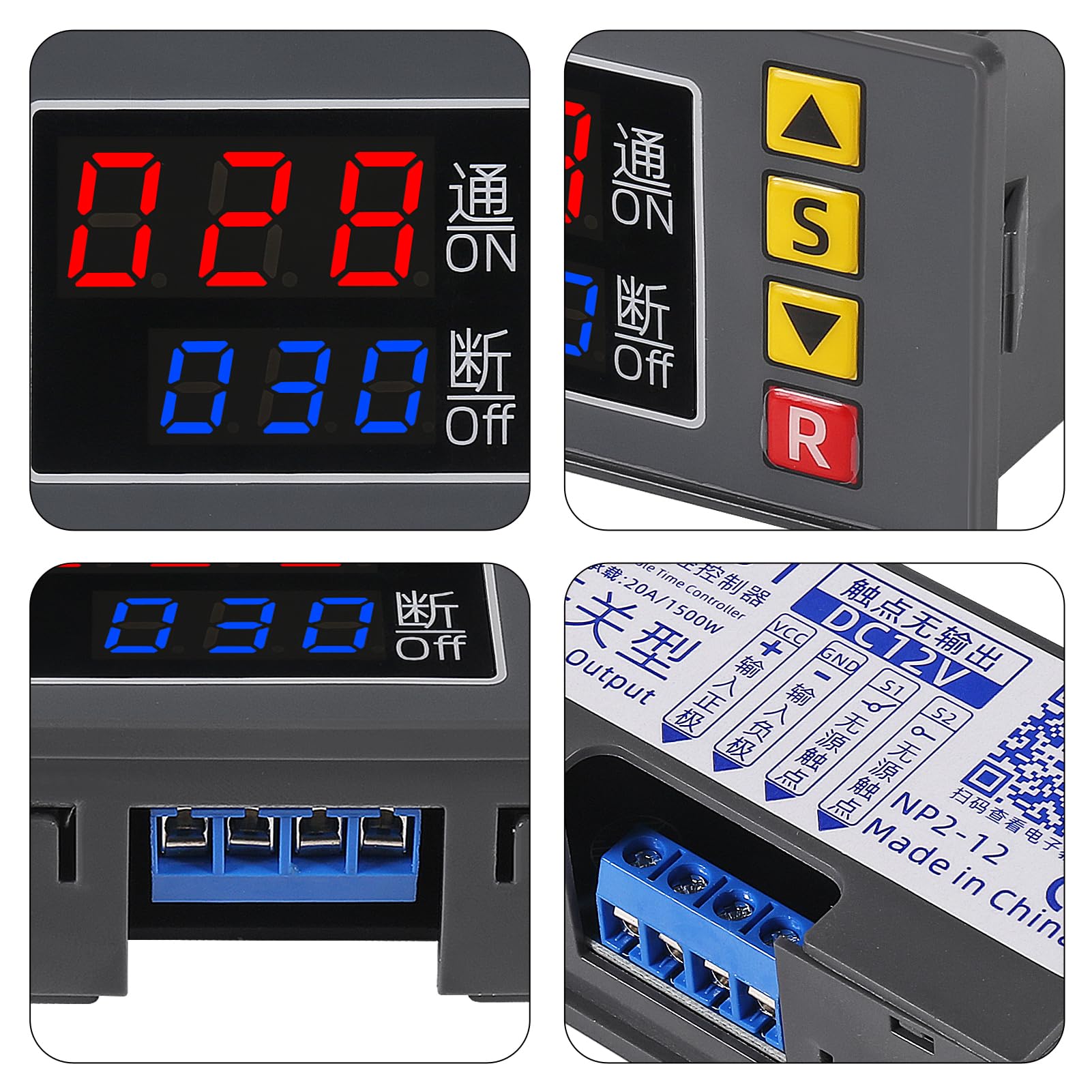
Great timer! Works well for a hot water recirculation system in a camper. I wired a doorbell button (momentary switch) to activate the timer to circulate hot water through the plumbing. I have the timer wired to shut off and remove power from itself after running for a set number of seconds. This prevents unnecessary draw on the RV batteries when the timer is not in use. Operation: 1. Momentary switch energizes timer circuit and included board-mounted relay, starts countdown, and retains power to its own circuit after momentary switch is released. 2. The timer circuit counts down to zero, cuts power to the relay and therefore to its own circuit stopping all power draw from the timer. Cycle repeats when timer is started with the momentary switch. Timer wiring legend (see photo): 12V+ ---Purple = 12vdc positive to power timer---tied to power supply +12vdc 12V- ---Green = 12vdc negative to power timer---jumper to yellow S1 ---Orange = 12vdc negative to supply side of relay---tied to power supply -12vdc (chassis ground) S2 ---Yellow = 12vdc negative to load side of relay---jumper to green Momentary Switch (doorbell button): Pole 1: Orange---(S1) Pole 2: Green and Yellow (12v- and S2) tied together Notes: Timer has non-volatile memory and retains settings after power loss. When activated, the relay on the timer circuit will pass thru whatever is attached on terminal S1 to terminal S2. I chose to use chassis ground (12V-) to activate the timer and water recirculation system. When timer counts down to 0, the relay is released and power to timer circuit is turned off (loss of ground). I only tested the countdown program that was needed for my recirc system. The terminal block is flimsy, but the timer was nine bucks, case included, and it works. I've attached photos of the circuit board product as of 2-26-2021 and a photo of my wires. Some assembly required. My unit came with the membrane front and the circuit board not fully snapped into the case. That's actually a good thing. They must know that my first step was to take it apart and see what's inside. :) The unit is easily assembled (snapped into place) once inspected. :) Instruction sheet was included. For a video on how the timer works, search for this: 4TTvfSYy204
J**.
does not set in tenths or hundredths of a second
I did not dislike the product. the time setting limitations were a deal breaker for me. The product func tioned well ,prompt service, it was mis ordered by me
M**N
It does work!
NOW That that's out of the way, One thing is, There is no INSTRUCTIONS! What you see on the image in the image bar doesn't explain that you have to jump the positive into the 3rd slot. Look up a YOUTUBE video! It took me awhile to figure this out without some instruction!
R**N
Worked...for a little while.
As others have mentioned a bit confusing to program but the Tube has some decent videos. My unit stopped working after only 10 -15 minutes of use. The load was far lower than it was rated. Powers on but will not switch the load.
L**L
Great Product
Arrived on time and packaged nicely. Item as described and worked for timing my cars A/C compressor to turn on and off for better performance since my temperature control module failed.
S**U
Great product
Bought this in an effort of controlling a solar panel system on my RV. The batts do not need to be charged daily if they are not in use (even though the controller should take care of it). While in storage, I have the batts refreshed for a few hours only once a week and ever since I installed this, I extended the battery life. For what I needed, this was a great product with lots of programming options.
K**R
Setup was a bear. More functions than I needed.
Setup was a bear, sketchy translation of the instructions didn't make things easier. It seemed that sometimes the buttons wouldn't respond to input. I struggled to program it, and luckily got it working but it was just dumb luck, and I probably couldn't repeat it. More functions than I really needed, but good luck figuring how to configure the bloody thing.
C**L
Needs an instruction sheet
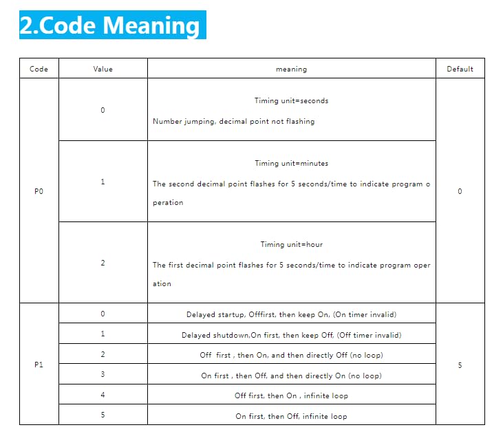
Could really use a short instruction sheet. I checked the reviews for this and other products and this is what I ended up documenting for myself: The timer delay settings are displayed/selected in units (seconds/minutes/hours) based on the P0 mode setting. The mode of operation (on/off sequencing) is based on the P1 mode of operation setting. To set the operation modes (P0 & P1): 1) Press and hold the set (“S”) button until “P0” is displayed. 2) Use the up/down buttons to select the timer unit selection (0=seconds/1=minutes/2=hours). 3) Press the set (“S”) button to select timer operation modes; “P1” will be displayed. 4) Use the up/down buttons to select the desired timer operation mode (0-5). See table for description of operation modes. To set the ON/OFF timer durations you need to: 1) Press the set (“S”) button twice quickly to access the timer setting mode. 2) Use the up/down buttons to adjust the desired “ON” time (displayed in red on the upper LED display). Holding the up/down button will rapidly increase/decrease the timer setting. 3) Press set (“S”) button to confirm the “ON” time setting and transition to selecting the “OFF” time setting. 4) Use the up/down buttons to adjust the desired “OFF” time. Holding the up/down button will rapidly increase/decrease the timer setting. 5) Press set (“S”) button once more to confirm the “OFF” time setting and exit the timer setting mode.
TrustPilot
1 个月前
1天前