⚙️ Ignite Your Creativity with High Voltage!
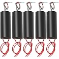
The Comidox 15KV Boost High Voltage Generator is a DIY kit designed for electronics enthusiasts, featuring a professional circuit diagram and components for building a high-frequency transformer inverter. With a maximum output of 15KV, this kit is ideal for various applications, including scientific experiments and ignition of combustibles. It supports input voltages from 3.7V to 12V, allowing for customization and flexibility in projects.
K**S
I just gana be blunt
I pay for it put it together and it doesn’t even work a waste of money if it not useable
P**Y
Very reliable
For such a small unit - it puts out great power- — By adding a cooling fan made it work even better for what I needed it for — plasma globe
R**C
simple medium-high voltage generator works
I received my order for the 15KV high voltage generator from Comidox and assembled it the next day. It does not come with instructions but it is a very simple circuit and I have reconstructed the schematic from the circuit board that was provided and in addition, I am supplying some tips and comments on construction. The key to the device is the stepup transformer with the secondary coil made of very thin wires providing the high voltage output thru red and blue insulated wires. In addition to the primary coil , there is a third winding of very thin magnet wire thatis the feedback winding that serves as input to the transistor (Q1) oscillator, connecting thru resistor, R1, and diode, D1, to the base of the transistor. Magnet wire is insulated thruout, and before assembly and soldering, clear off the insulation at the ends of the primary and feedback windings well wind sandpaper or steel wool so that solder can stick and a good connection will be made. Another critical step is polarity of the feedback signal from the feedback coil (coil with thinest wires for connection), To work at all , you need positive feedback so the transistor will oscillate and generate an AC input into the primary turn of transformer so it can be stepped up to high voltage. So if it doesn't work you may have to reverse/interchange your connections to the feedback coil.Now how do you know if it is working? taking an electric shock is NOT a safe way to find out. I have an oscilloscope so I can build a simple 1000:1 and even 10,000:1 resistor down divider to reduce the voltage and observe signal waveforms at a safe level. Another option is to connect a miniature neon bulb to a 1 Megohm resistor in series and see if the neon bulb lights up when connected across output Red and Blue leads of the HV generator. If you have good hearing at high audio frequencies , I found that that the HV generator makes a hum when operating properly when assembled using the 120 ohm resistor for R1 that is supplied. I think this hum is made by the transformer iron frame responding mechanically to AC current that must be generated . No hum could mean no AC current generated and you may have to reverse/interchange the feedback coil connections.One final comment. For my application- protecting some plants from small animal predators, I didn't need 15KV, and even 1 KV is more than enough so I am operating HV generator on only 3 volts supplied by batteries and increased my base resistor R1 to 680 ohms. reducing base current by increasing R1 , reduces HV output and also decreases power consumption and heat generated by HV generator circuit. It is safest to keep HV at the lowest value needed for your application. I hope this helps.
F**S
worked only when i did it without pcb
great but pcb does not work
B**A
Great high voltage device.
I got these for a mini Tesla coil experiment and yes it work however there is no instructions. I can see how that would be very difficult for a beginner. But all in all it works like the listing says.
Trustpilot
2 days ago
5 days ago