We remain fully operational. Our teams are working around the clock to ensure your deliveries continue safely.

DOWNLOAD THE APP


Customer Services
Copyright © 2025 Desertcart Holdings Limited
DOWNLOAD THE APP
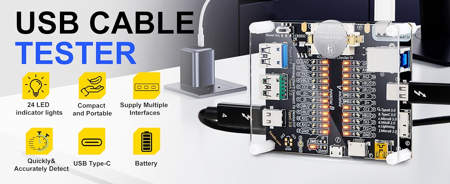
🔌 Test smarter, not harder — the ultimate USB cable truth-teller!
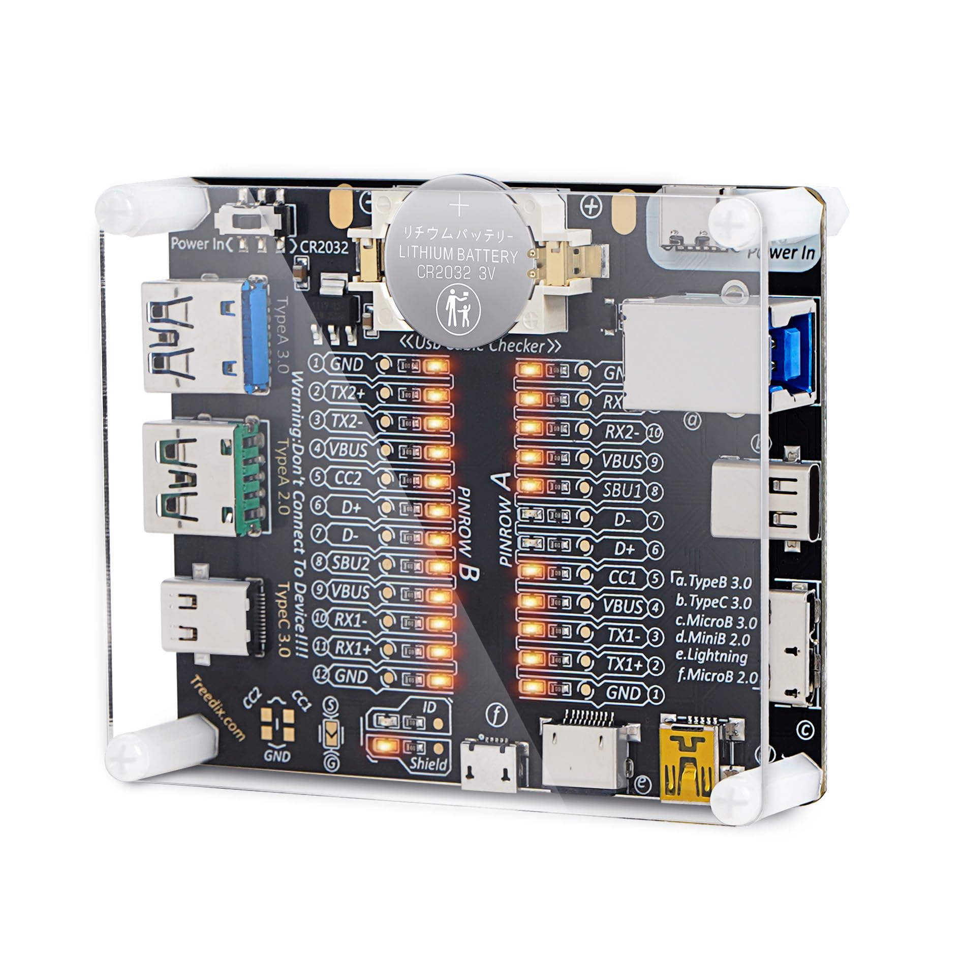
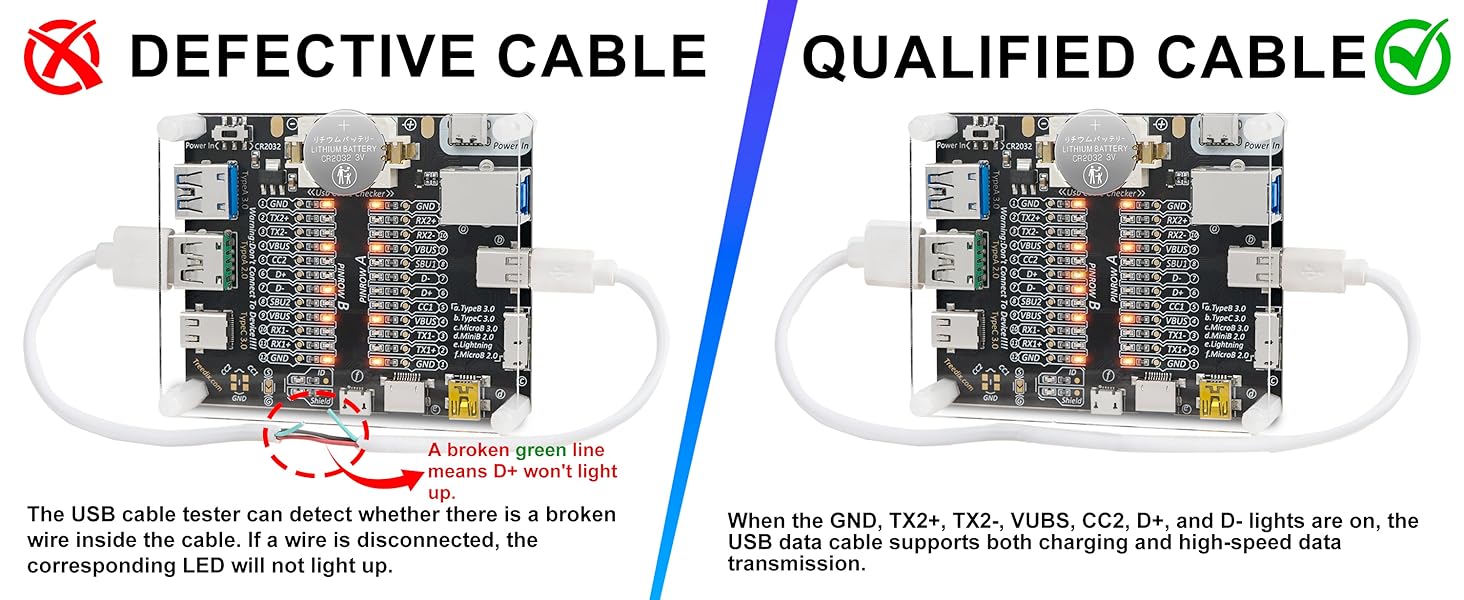
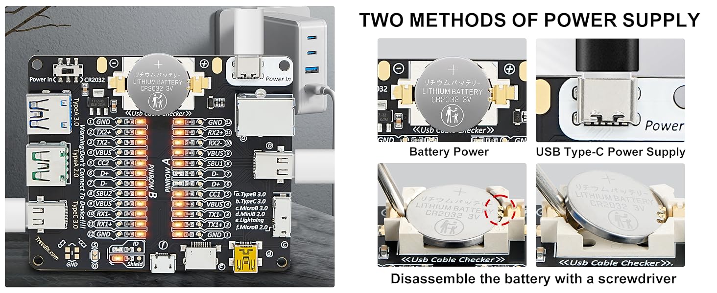
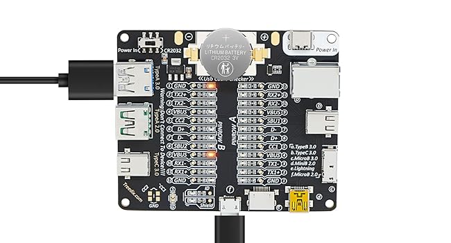
The Treedix USB Cable Tester Board is a compact, battery-powered diagnostic tool designed to test a wide range of USB cables including Type-A, Type-B, Type-C, Micro, Mini, and Lightning. Featuring 24 LED indicators, it provides detailed pin-by-pin status to identify faults, shorts, and compatibility issues. Its durable acrylic case and dual power options (CR2032 battery or USB-C 5V) make it a portable, reliable solution for professionals seeking to ensure cable integrity and avoid counterfeit or faulty products.

| ASIN | B0CF95VL2Y |
| Batteries | 1 CR2 batteries required. (included) |
| Best Sellers Rank | #4,164 in Industrial & Scientific ( See Top 100 in Industrial & Scientific ) #6 in Network & Cable Testers |
| Brand | Treedix |
| Color | Transparent |
| Date First Available | August 9, 2023 |
| Item Weight | 0.32 ounces |
| Item model number | USB Cable Tester with Acrylic Case |
| Manufacturer | Treedix |
| Min. Operating Voltage | 3 Volts |
| Package Dimensions | 3.54 x 3.15 x 0.94 inches |
| Power Source | Battery Powered |
| Style | USB Cable Checker with Acrylic Case |
| UPC | 644197770089 |
M**O
One Beefy Little Guy! (Showcase of Device and Manual For Pins Included) :)
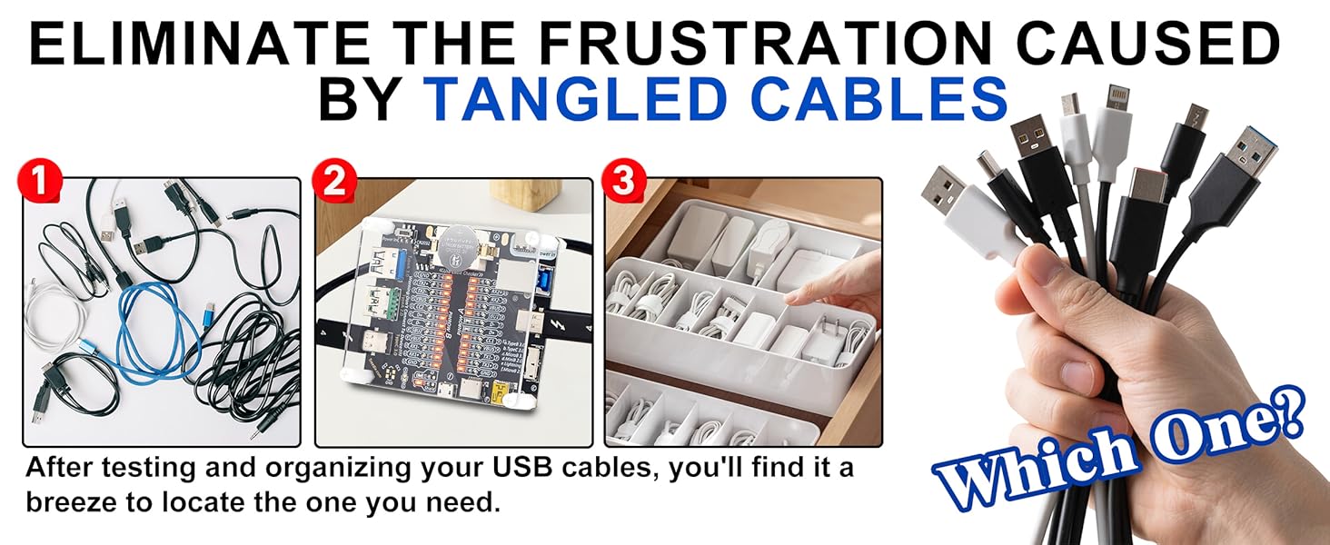
Important Warning: DO NOT use this tester to connect to live devices. Doing so could potentially damage both your devices and the tester itself. It is designed solely for testing cables as intended. --------------------------- ★ Section 1 - The Review ★ • This is by far the best design I've encountered for a cheap USB cable tester. It features a straightforward circuit powered by a CR2032 battery or via a Vin pin (cable not included). Each pin of the cable connects to a corresponding light that illuminates when a cable completes the circuit. I really appreciate the broad range of compatible ports, including USB Type-A 2.0 and 3.0, Thunderbolt 3/USB Type-C 3.0 on both sides, Lightning, Micro-B 2.0 and 3.0, and Mini-B 2.0. These standards are fully backward compatible, and the inclusion of both versions ensures that this tester is 100% reliable. • The board has two sides: "Side A" and "Side B," accommodating the reversible nature of Type-C cables. For other types such as Lightning, Micro-B, Mini-B, typically only one side will light up. Generally, you should focus on the side with the most lights illuminated; the other side can usually be disregarded, except for Lightning cables. • One area for improvement.. It would be the documentation of expected pinouts and explanations of the different common combinations. However, this can easily be resolved with a quick Google search. I’ll share my understanding and research below. --------------------------- ★ Section 2 - Here’s a breakdown of what each of those pins means ★ GND (Ground): This is the reference point for electrical signals in the circuit. It serves as the common return path for electric current. • TX+/- (Transmit): These pins are used for data transmission. "TX+" is the positive data line, and "TX-" is the negative data line. They work together to send data signals. • RX+/- (Receive): Similar to TX, these pins are used for receiving data. "RX+" is the positive line for incoming data, and "RX-" is the negative line. They allow the device to receive signals from another device. • VBUS: This pin carries the main power supply voltage. It typically provides +5V to power devices or charge them. • D+ and D-: These are the data lines used in USB connections. "D+" is the positive data line, and "D-" is the negative data line. They enable data transfer between devices. • CC1 and CC2 (Configuration Channel): These pins are used in USB Type-C connections to determine the orientation of the connector and negotiate power delivery. They help devices communicate their capabilities to each other. • SBU1 and SBU2 (Sideband Use): These pins can be used for additional features, such as audio or alternate modes, depending on the type of device connected. They provide extra functionality in certain situations. • ID (Identification): This pin is used to determine the type of device connected. In certain configurations, it helps differentiate between host and peripheral roles. For example, in some USB OTG (On-The-Go) setups, the ID pin can signal whether the device should act as a host or a peripheral. • Shield: This pin is used for grounding the shield of the cable, which helps reduce electromagnetic interference (EMI). It helps protect and improve the signal integrity by grounding any external noise that may affect data transmission. --------------------------- ★ Section 3 - A valuable diagnostic tool for several reasons ★ • Signal Integrity Testing: It helps verify the quality of data transmission through the USB cable, ensuring that signals are not degraded. This is crucial for high-speed data transfer applications. • Pin Configuration Verification: The board can confirm that all the necessary pins in the USB cable are properly connected and functioning. This is important for ensuring compatibility with devices. • Identifying Faults and Damage: By testing various cables, you can quickly identify any faulty ones. This is helpful if you suspect that a cable is defective or if a company is providing subpar products. • Compatibility Checks: It can help determine if a cable is compatible with specific devices, preventing the use of cables that might cause performance issues or failures. • Preventing Scams: If you're considering purchasing cables from a vendor, using the test board can help you confirm that the cables meet advertised specifications. Then you would know to return the product for a full refund, and purchase a different cable from another vendor. This can protect you from scams where companies sell low-quality or counterfeit products. • The Frustration Caused by USB Cables: Want to organize or discard cables, but don't know which ones are functional? You can use the USB Cable Tester Board to easily help you identify the right cables to keep.
P**Y
Great. For the price? Can't beat it.
Looks like many of the negative reviews are old. This came right up and worked for me. So here goes: 1- Not easy but not hard either to peel off the protective backing from both sides of the clear top. 2-Assembly took fewer than 5 minutes. Might take you 10 if you're ham-handed. 3-Battery: easy enough to remove the battery with a pocket knife point on the left side (towards the USB A connectors), remove the insulating strip and snap the battery back in. Pry out from top-center-left. Should be simple to do the same when changing the battery. 4- Slide the power switch towards center to turn on. No lights at all until you connect a cable that's at least partially good. Mine worked right away. 5- Tests the shield too. 6- If you're buying this for continuity testing, you're home free. 7- Should perhaps have included a female pigtail for power supply but CR2032s are so cheap, why bother with an external supply anyway? Battery should last a good long while. Great price, does the job, identifies open and intermittent conductors (haven't found a shorted cable yet but it probably shows you those too). I've already tossed out a couple of bad cables and have a good idea of which are good. Can't ask more for under 20 bucks.
J**E
i like this device I'm a little sad with the support but the device works well
I, like everyone else have a ton of cables it feels like i have millions but I know that's an extreme exaggeration. but i will say i have a lot and like you i've collected these various cables throughout the years making some of them great at the time, but now extremely outdated. The other problem is they all look a like and unless you have some kind of beautiful mind you can't remember what products they work with or what year or genteration or blah blah blah. So my friend told me about this and i purchased it and i have to say i've been going through my cables and have been surprised with what i thought were good cables and the cables that have stood the test of time!! It is easy to use and comes to you fast so you can get it really quick if you're in extreme needs!! My only problem with the item is that I'm not your hardcore computer programmer electrical engineer savant. Im very tech savvy and don't have alot of problems figuring things out if i don't know them. with the exception of this device. It gives you a ton of information, but if you don't have a background in Computer science or you're not a 8 year old prodigy hacking your elementary school to change your planned recess time, then your kind of on your own!!! Like i said there is alot of info the board gives you , but there is no guide to what that info means. I guess your just supposed to know that!! i tried reaching out to support and never got a person at all, and i even email the support address they give you and nothing. the website wasn't much help either, i couldn't even find the product on their own website??? it has a guide that tells you how to connect the cables and and what it's used for but interpreting the results. your on your own!! It would be nice if there was a little guide or map of what the different lights mean and how that corresponds to the actual cable you are testing. Meaning if i have a board where 20 of the lights are lit up what kind of cable is it? what is it capable of, and what is it not capable of as well. As it is you hook up the cables and the lights come on and that's it. like i said gifted coders and such im sure have no problems interpreting the results, but the rest of us would like a little bit of info about what we are seeing!! and since contacting support has been a bust, you're left with google to try and figure it out for yourself!!! hope this helped every that are on the fence about this product!!
G**E
Just the best wire Tester ever. It works beautifuly. And, looks amazing. I'm going to buy another one in case I brake the one I have. Thanks
M**N
I bought the option with cover so some assembly required. Works as advertised. It’s helped me organise my usb cables.
M**O
De facil uso, permite rápidamente determinar si el cable funciona adecuadamente y que tipo de cable es
W**C
Has an on board connector for power - but nothing to mate to it and actually provide that power. Quite ridiculous. I have seen reviews saying the button cell battery cannot be removed - but actually it can and quite easily so. My main gripe is flux on the printed circuit board because it hasn't been washed off during manufacturing so if you see greasy spots on the circuit board and /or the soldered joints it is flux. To add to this the leads of the components don't pass through the holes far enough so can't be properly soldered to the board. You can buy a device off a well known Asian supplier for a fraction of the cost and sure it's quality isn't much worse but there is a big difference in price. With plenty use I can see one or more of the connectors coming off the Treedix board - probably taking some track with it and for all intents and purposes (except for the die hard DIY repairers) rendering it scrap. At least with the alternative suppliers in Asia they are a fraction of the cost and the loss is much easier to take.
M**L
USB cables come in all kinds of capacities. This lets you quickly know if a cable is for power only (apple Vision Pro for example) or whether it has data capabilities and so on It’s interesting to use
Trustpilot
1 month ago
2 months ago