⚡ Ignite Your Curiosity with a Spark of Science!
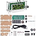
The WWZMDiBMini DIY Tesla Coil Kit is an innovative electronic project designed for adults, allowing users to practice soldering while exploring the fascinating world of plasma and wireless electricity. This kit features a 3.5mm audio input for music playback, the ability to light fluorescent lamps, and creates stunning arcs, all while ensuring safety during operation.


| Item Dimensions | 1 x 1 x 0.5 inches |
| Size Name | Fun DIY Soldering Kit |
| Theme | Physics |
E**D
Excellent Value and Fun to Play With
The media could not be loaded. For $10, this is a nice little fully-functional Tesla coil kit! It is relatively low power, so the arc is small, but it is indeed a fully-functional Tesla coil.I was able to light the included bulb, along with a fluorescent light bulb, and the fluorescent light bulbs on my workbench.Assembly is mostly straightforward, but make sure the primary windings are not too close to the secondary, otherwise the secondary will arc to the primary, possibly damaging it. I had several arcs, but it does not seem to have damaged it (other than a black mark). I 3D-printed a small spacer to keep this from happening again.The power supply is important. At first, I was using a 15V supply, but I seem to get better results with a 24V, 6A power supply.Playing music through the arc works as advertised. Keep in mind that the volume level is very low, but you can indeed clearly hear the music being played in a quiet room.Overall, I am very pleased, and this was well worth the money. My kids and I spent hours playing with it. In fact, I bought a second one so that I can experiment with it, without worrying about breaking my original one.Pros:* Great value for the price* Fun to play withCons:* Make sure you have a beefy enough power supply. I recommend 24V, 2.5 A minimum.* Assembling the primary windings can be tricky -- ensure you have the correct number of turns, in the correct direction, and at a sufficient distance to prevent arcing, but not so far away to decrease coupling efficiency.You can find the the 3D-printed primary coil spacer I designed on TinkerCad by searching for "Tesla Coil Winding v2".
S**.
Directions are misleading and inaccurate.
This Tesla coil may work provided you build it according to the picture in the instructions and not the written part. My partner soldered this up according to the written part… Tesla coil does not work. The resistor “color wuheel” descriptions for the 2K and 10K resistors are incorrect. For 8 bucks or whatever it’s not worth it to de-solder the resistors and correct it. 1 star for the practice soldering. Don’t buy, look for another brand.
J**J
It was ok
Good solder practice, item worked for a day or two and then stopped working.
E**W
Nice first project for Jr High kids
Pic was a little deceiving. It’s pretty small. When together it performed. Nice project kit.
A**R
Works mostly but there is a gotcha
My kit was missing a 1.0uF electrolytic cap and one of the red LEDs. The biggest problem with the design is that the feedback to the transistors are polarity dependent. This means the current direction in the coil matters. The first two pictures show that the red (primary) loop are in the same direction as the secondary but one direction works and other other doesn't. If the 'arrow sticker is counter clockwise then the Tesla coil doesn't work for me.The instructions doesn't mention LED2 which is basically power and LED1 indicates the amount of current being drawn from the Tesla coil.Hacks and improvements. First, I put a small connector on L2 terminal so I can disconnect the coil without needing to desolder it. The wire is fragile and for storage you would like to disconnect the coil so it can lay horizontally. Second, I added 7 ceramic caps to the power supply traces on the bottom. The 7-caps compose of three 10uF 25V, two 0.1uF 50v and two 10nF 100V. These will greatly help with short pulsed current needed which will enhance efficiency and increase output voltage. Adding electrolytic caps will be of lessor value since their internal resistance and inductance will be to high to be helpful. I scratch through the solder mask and soldered down a little bit of copper tape on both sides of the power traces to mount 0805 SMT caps. You might not need the copper tape if you use 1206 or 1210 caps. Be careful if you use magnetic wire and additional windings as the back EMF might breakdown (destroy) NPN TIP41C transistor. If it is damaged you'll have continuity between the 1st and 2nd pins and between 1st and 3rd pins. This happened to me and I had to replace the TIP41C to make it work again.There is a typo in the instructions, the small cut out parts list and the silkscreen on the PCB are correct with listing the NPN transistor as TIP41C, but the instructions incorrectly lists it as TIP42C which is a PNP.The unit worked fine with a 12v DC 1A power supply.
J**S
Fun little project
The media could not be loaded. I suspect the bad reviews are from people who didn't pay attention to details. It works and plays the radio through the headphones jack. It gets hot at 24 volts so I don't run it very long.
M**M
It doesn’t work.
Junk. Does not work. A waste of money.
T**E
Poor instructions, disappointing results
The arc is barely visable, kind of a let down after soldering it all together, and getting a suitable power supply. Really not worth the money.